
HUETHERTECH develops innovative sheet guidance system
The development is co-financed by the European Union’s Individual Innovation and Technology Support Programme and the state of Rhineland-Palatinate.
The project aims to expand research and innovation capacities and introduce advanced technologies.
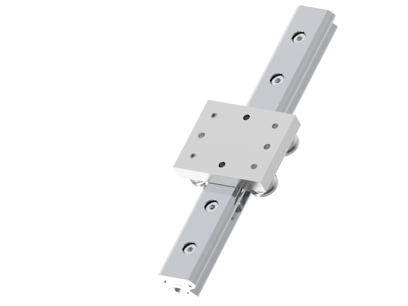
Track roller guidance systems
HUETHERTECH track roller guidance systems are built for linear motion applications and are characterized by their durability and silent operation with little need for maintenance.
These properties make these linear guidance systems indispensable components in mechanical engineering and fixture construction.
The linear guides form the heart of highly developed machines, but also in simple devices or equipment and are used across all industries.
Track roller guidance systems are easy to assemble, require little need for maintenance, and can be put into operation very quickly. Given their modular design, track roller guidance systems are also suitable for applications with very long travel distance.
The system components include the support rails and the carriages.
The linear guide is delivered ready to screw on. The customer has the option of attaching the guide rail from above or below.
Vertical and horizontal movements are possible even in dirty and rough environments. Safe operation and a long service life are guaranteed with only low maintenance.
Range of application: The track roller guidance systems can be used at speeds of up to 10 m/s.
New
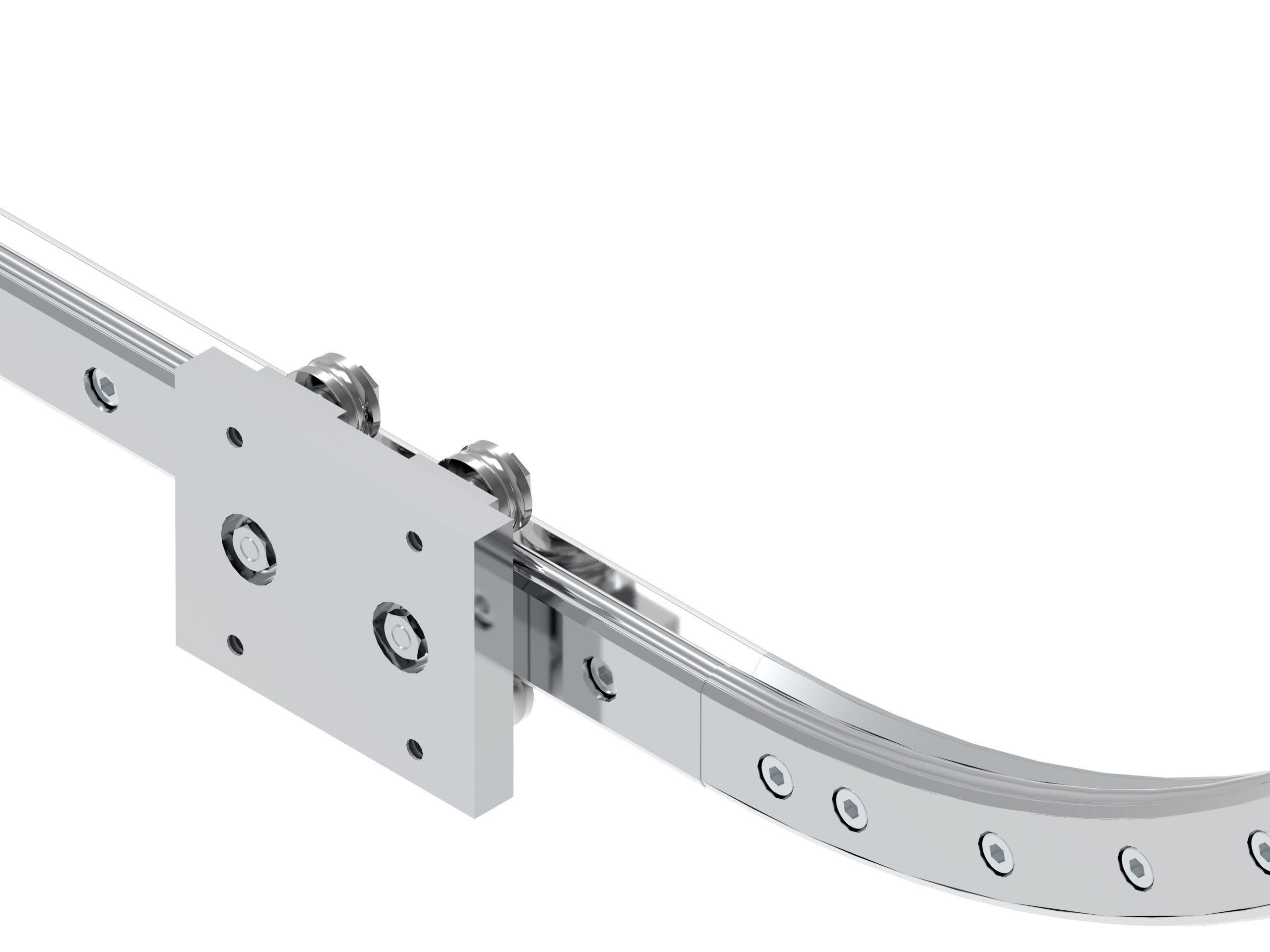
Track roller guidance system with bogie carriage
It’s not always the case that a linear guide must only realize the direct path from a starting point to an endpoint. Transport often takes place in a non-linear motion, right up to a circular path. With the straight guide rail in combination with the curved segments, there are hardly any limits to the directions of motion.
Installation
Position the support rail and fasten it hand-tight. Align the support rail. If necessary, press it against a stop edge and screw it tightly into place. Apply the correct tightening torque according to the table. Bring the carriage into position. Adjust the clearance to the guide rail using the eccentric bolt: Tighten clockwise. The track roller must be set against the raceway.
Lubrication
The rolling rack between the support rail and the track roller must be lubricated to avoid damage caused by tribocorrosion.
The required lubrication intervals for the support rail raceways depend on the surrounding conditions. The cleaner the surroundings, the less lubricant is needed. The correct interval and precise amount of lubricant can only be determined under operating conditions, since not all conditions can be calculated in advance.
The system must be lubricated at the latest whenever tribocorrosion occurs. This can be recognized by a reddish discoloration of the mating track or the outer ring. Afterwards, the lubrication intervals must be reduced.


Support
The HLFS support rails is designed in a composite construction. Two polished precision steel shafts are fixed in an aluminum base element.

